| Maat-ka-Ra Hatshepsut |
| Transport
The illustrations in the southern wing of the 1. Portico show how the two obelisks produced in Aswan were transported to Karnak on a double-ship that was dragged by 3 x 9 tugs with probably 864 rowers. However, the scenes in Deir el-Bahari probably show the arrival of the obelisks at Karnak from view of the artist. The technology of the double-ships was described in detail by Wirsching (Wirsching, A., "Das Doppelschiff - die altägyptische Technologie zur Beförderung schwerster Steinlasten", SAK, volume. 27, 1999). The technology was in use since the 4. Dynasty. In the Old Kingdom loads up to 60 t were carried this way, the obelisks carried in the New Kingdom weighed many times the amount (the obelisk of Hatshepsut weighs approx. 323 t). Although this technology was probably frequently used, there are - according to Wirsching - altogether only three representations which show the transport of heavy loads by ship: - a scene in the tomb of Senedjem-Ib, 5. Dynasty, shows the transport
of a sarcophagus, From the time of the 18. Dynasty there also exists a written
report: Ineni (see Persons),
who has been the overseer of the construction work in the temple of Karnak,
reported that he - on behalf of Thutmosis I - was responsible for
the building of a ship of approx. 63 m length and approx. 21 m width
for the transport of a pair of obelisks (Wirsching, loc. cit.).
|
| Technique of the double "Double-Ship" (drawing from Wirsching, 1999); upper part: unloaded, lower part: loaded |
| The remarkable fact that the relief in Deir el-Bahari does not show
this technology, explains Wirsching with the assumption that:
1. the illustration along the causeway of Unas served as model for the relief in Deir el-Bahari and 2.that the relief does not show the actual arrival of the obelisks but the ceremonious production of their arrival! At least for the 1. assumption Wirsching seems to have some evidence because obviously some picture elements of the ships of "Unas" (e.g. sledges below the obelisks which were used to transport them ashore and the protection bandages) had been transferred to the relief in Deir el-Bahari although they would have been useless in the case of transport on a double-ship. |
| Erection of Obelisks
From the obelisks set up formerly in Egypt today only 4 are still standing on their original place, 2 in the temple district of Karnak (one of Hatshepsut and one of Thutmosis I), one in front of the temple of Luxor (Ramses II), and one in Heliopolis (Senwosret I). The is no Egyptian text that describes how the obelisks were put up. However, modern engineers had the "same" problem. On behalf of Pope Sixtus V. the architect and engineer Domenico Fontana erected in the years 1586 -1589 three obelisks in Rome which had been brought from Egypt to Rome in the years 10 B. C. and 47 resp. 357 A.D.. Fontana let construct two parallel scaffoldings up to the full height of the standing obelisks. Both scaffoldings were interconnected on the upper level of their joists. An obelisk was erected between the two scaffoldings while the upper end (upper third) was raised with ropes and at the same time the lower end (lower third) of the obelisk that was lying on a car was drawn through the scaffoldings until its basis reached the final position and the obelisk tipped over into the vertical position by the gravity. 1836 M. A. Lebas erected in Paris (on Place de la Concorde) the obelisk of Ramses II which were brought from the temple of Luxor to Paris. Lebas had noticed in Luxor that on the surface of the base a notch (groove) ran parallel to the edge of the base. He assumed that one edge of the basis of the obelisk was set into this groove and that the obelisk was moved into the vertical position by turning is in this groove as in a joint. Accordingly, he let raise the obelisk in Paris with levers and turned it upright around the edge. Dixon (1878 in London) and Gorringe (1880 in New York) used the same procedure. They raised the obelisk horizontal until it reaches the supposed height of its center of gravity then they turned the obelisk around this center into the vertical position. |
| After the modern experiences of putting up an obelisk the optimal procedure seemed to be the trick to turn it around its center of gravity or around an edges of its basis. Several deviating procedures were discussed nevertheless. As example the procedure suggested by Arnold (1994) should be described here briefly. |
| Arnolds suggestion is a modification of the procedure after which the obelisks had been approached on dams and then were lowered from the edge of the dam down to the basis (see drawing above, from Arnold, 1994). Arnold took into consideration that large dams, which were suggested in other procedures, could probably not put into practice due to the closely built-up area of the temples. Also in his suggestion the obelisk is in the last phase moved into the vertical position (see above) by turning it around the groove in the basis. However, Arnold did not say anything about the control of the forces and the guidance of the obelisk when putting it up. |
| On the basis of the modern experiences and a description
of the scribe Hori (in the papyrus Anastasi I) about how to put up a large statue Wirsching examined
whether the Egyptians could erect obelisk in a similar
way i.e. by turning it upright around its basis.
According to Wirsching (Wirsching, SAK 28, 2000) the obelisk was raised in 2 phases resp. turned into the vertical position. For the 1st phase two retaining walls had to be built along the sides of the obelisk. For the 2nd phase a third - transverse - wall at the basis of the obelisk was needed. At the beginning the obelisk lies in a long "chamber" surrounded by three walls (see below). |
| "Chamber"-model according to Wirsching, 1. phase turning of the obelisk; on the left a top view on the "Chamber", on the right a side view (with an obelisk lying in the chamber); drawing: Wirsching, SAK 28, 2000 |
| In the 1st turning phase the obelisk which is resting upon the base is lifted resp. turned around the groove of the base by ropes lead over the longitudinal walls until it has reached the height of the longitudinal walls (see below). The required strength is produced by counterweights of stones at the ropes which can be controlled lowered on the exterior of the walls. The final position of the 1st turning phase is shown in the drawing above by dotted lines. |
| "Chamber"-model of Wirsching, 2. turning phase; drawing: Wirsching, SAK 28, 2000 |
| In the 2nd turning phase the obelisk is turned into the final position by ropes which lead over the transverse wall behind the base and are charged with counterweights (see design above). In both turning phases it is necessary to control the traction power at the ropes. The most power for putting up the obelisk is required at the beginning the 1st turning phase and becomes increasingly smaller with an increasing vertical position of the obelisk. The decrease of the necessary strength was controlled by the individual length of the ropes which were measured in such a way that each counterweight hanging on it touched down on the ground when its traction power was not needed any longer. According to Wirsching the additional power of people was needed only to slow the last momentum when the obelisk tilted due to its own weight into the vertical position. |
| In his
"chamber"-model Wirsching took also into account a problem that was frequently ignored. All bases
of the obelisks in Karnak have - according to Borchardt (quoted after
Wirsing, 2000 ) - slots in similar execution. The
slots are approx. 20 - 30 cm wide, 6 - 10 cm deep, and somewhat longer than the
lateral edge of the
obelisk. In the cross-section the slots are wedge-shaped whereby the side at the
obelisk is steep and the side at the outer edge of the base shows a flat
slope - thus, the obelisk
stands at the steep, rear edge of the groove. This has led to the assumption that the obelisk was latched
with its lateral edge on the groove during the rotating
into the vertical position. This, however,
would have certainly damaged the edge on which the whole weights of the
obelisk would have rested - it probably would have splintered to
pieces. According to Wirsching a semicircular joint of hard material (possibly from basalt or bronze) was inserted into the groove (with the flat side into the groove resp. with the semicircular side upward; see below). As counterpart or socket served a ledge at the lower edge of the obelisk which was left there during its production. In both phases the obelisk was rotated in this joint construction whereby the extreme load on the edge of the obelisks was avoided. In addition, while the obelisk is raised it also develops due to its large weight a rather large horizontal thrust - in the illustration below directed to the left side. The joint construction prevents - apart from the load of the obelisk's edge - also that the obelisk slips away over the base to the left side due its own weight. Since at none of the existing obelisk a socket was found the parts jutting out have probably been chiseled away after the erection and the joint removed from the groove. |
| Basis with groove, joint, and socket at the basis of the obelisk; on the left the obelisk is still lying, on the right it is in the upright position (drawing: Wirsching, SAK 28, 2000) |
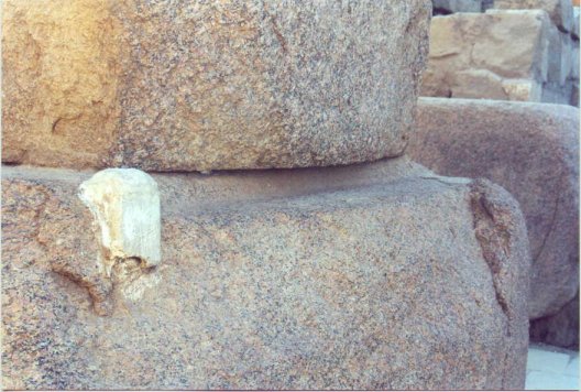
| The groove at the basis used during the erection of the obelisk which is still visible here at the basis of the obelisk of Thutmosis I in Karnak. |